Most of all the electrical wiring is complete. Some small parts remained that I needed to complete.
The hidden relay functionality
There is a great Facebook group regarding lithium batteries on boats. After my installation of the battery pack, I posted a comment regarding my Lithium installation. I can recommend anyone considering lithium to join this Facebook group.
https://www.facebook.com/groups/427372107686109/
I got a lot of positive comments and also some good recommendations. One was to add compression to the battery pack that I will do some time later. I am not overly concerned about compression since I will use very conservative settings for both over voltage and under voltage.
But one of the comments was to automate overvoltage protection on battery pack level using what I had already installed. The manual of the BMV-712 battery monitor is not very detailed about the relay functionality. But after researching a bit, I figured out how to use the relay on the BMV-712.
By connecting a relay cable from the battery monitor to the switch of the ML-RBS remote battery switch, I could trigger the ML-RBS to disconnect the battery if the BMV-712 measures an overvoltage event on the battery pack.
To not over complicate the wiring I ran the wire from the battery monitor to the remote switch instead of to the battery switch. I got a couple of questions from the facebook group of the wiring. I’m posting them below for others to see as well.
- Always-on bus bar -> BMV-712 (COM)
- BMV-712 (NC) -> Contura Remote switch (Pin 1)
Since I am using the ML-RBS 7700 I am not using inverted settings on the BMV-712 and the NC (Normally Closed) relay connection from the BMV-712 to the Contura switch.
If the overvoltage is triggered, I have to manually connect the battery by pushing the remote battery switch. This will not be done automatically. But I figured that if an overvoltage event is triggered, I still want to investigate a bit before the battery pack is connected again.
BMV settings
The BMV-712 needs some specific settings when you use the BMV with Lithium batteries since they have a much higher charge efficiency.
Some friends have been using Pukert exponent 1.03 and Charge efficiency factor: 98% with excellent results together with their lithium Winston cells or Winston 12V batteries. These settings are slightly different from the recommended settings from Victron. I will start with the recommended settings from Victron and see if I need to adjust them over time
Current settings on the Victron BMV-712
- Battery capacity: 320Ah
- Charge voltage: 14.0V
- Tail current: 4.00%
- Charged detection time: 3m
- Pukert exponent: 1.05
- Charge efficiency factor: 99%
- Current threshold: 0.10A
- Time-to-go averaging period: 10m
- Relay mode: Default
- Invert relay: Off
- Minimum closed time: 0m
- Relay-off delay: 0m
- Low SOC relay
- Low voltage relay: On: 11.6V, Off 11.7V
- High voltage relay On: 14.6V, Off 14.2V
- Alarm buzzer: on
- Low SOC alarm On: 10%, Off: 12%
- Low voltage alarm On 12.6V, Off: 12.7V
- High voltage alarm On: 14.5V, Off: 14.2V
Mounting and configuring MultiPlus inverter/charger
The mounting and wiring were all prepared for the Multiplus. The only thing that remained was to program the Multiplus and then do the actual mounting.
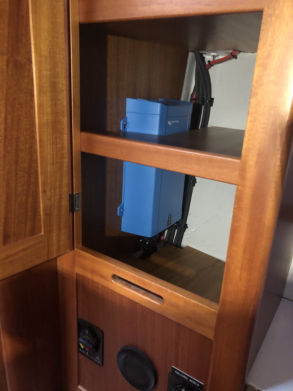
The mounting is not ideal in a cabinet, and there might be some issues with cooling. I don’t expect to use either the inverter or the charger all the time. But I will have to monitor the temperature to see if there will be cooling issues.
There are some dip-switches on the Multiplus. But that would only enable some settings and would not allow the charge profile that I wanted to use. The charge profile for lithium using dip-switches would set the absorption to 14.1 V and the float to 13.8 V which is too high for my preference. I would also not be able to set the charge curve with the dip switches.
My initial plan was to borrow a USB to VE.Bus converter. But I later reconsidered and ordered my own since I might fiddle with the settings after some testing and adjust them over time.
The current settings used after configuring the Multiplus using VE.Bus
- Lithium batteries: Checked
- Use equalization: Not checked
- Charge curve: Fixed
- Absorption voltage: 13.80 V
- Float voltage: 13.30 V
- Charge current: 37 A
- Repeated absorption time: 1 Hr
- Repeated absorption interval: 14.00 Days
- Absorption time: 1 Hr
These settings will make the battery pack stay below and never reach 100 % SOC. But that is something that I prefer. It will also disable the Float since the float setting is too low to start. Neither charging to 100 % of SOC or using Float is something that I want.
Configuring MPPT
I had already installed the MPPT. Since the SmartSolar MPPT 75/15 is connecting to the Victron app using Bluetooth, it’s effortless to configure the settings on the MPPT.
Current settings on the SmartSolar MPPT 75/15
- Absorption voltage: 13.90V
- Maximum absorption time: 6h 0m
- Float voltage: 13.20
- Equalization voltage: 0.00V
- Temperature compensation: Disabled
- Low temperature cut-off: 10.0°C
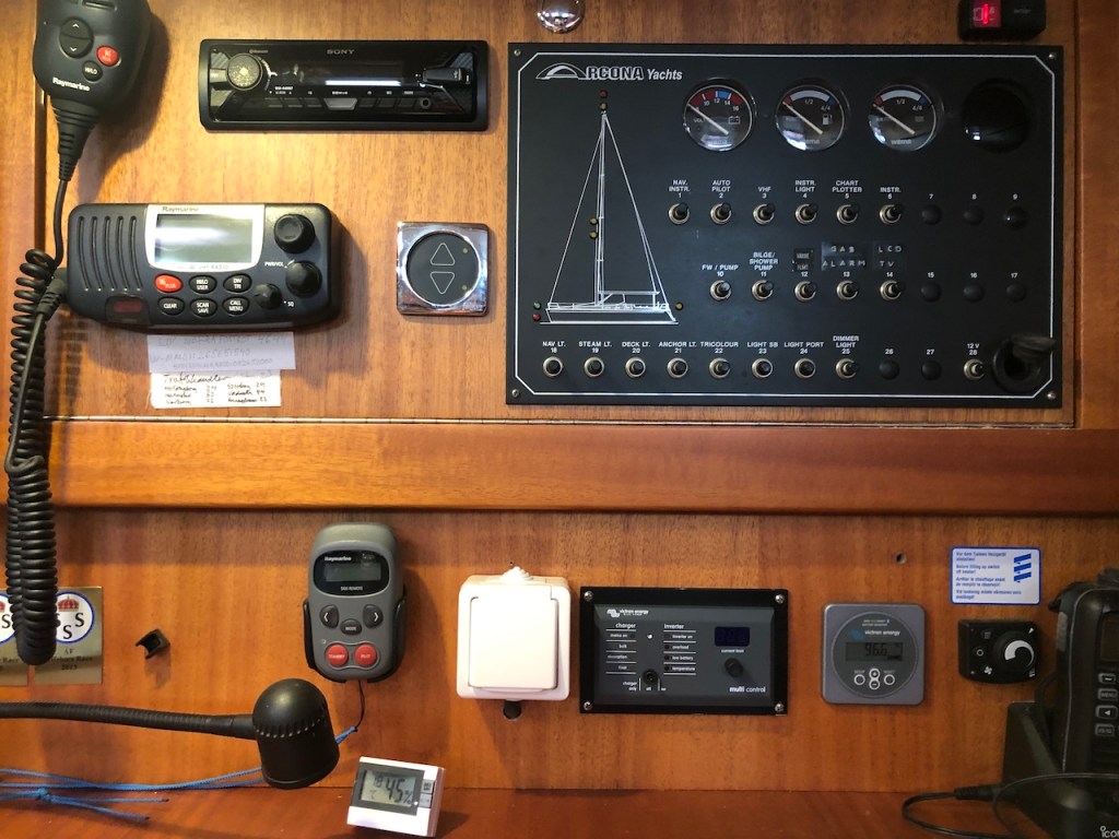
Ugly hole and charger/inverter control panel
When I mounted the new BMV-712 battery monitor, I used an existing hole for an alreaç÷dy disconnected TV-antenna socket. That left me with an ugly old hole underneath the DC panel from the old battery monitor.
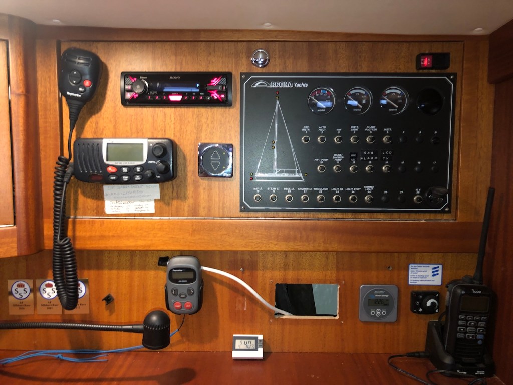
Since I don’t always want to charge the battery pack when the shore power is connected as well as reduce the power consumption from the inverter when it’s not used. I wanted an easy way to switch both the inverter and charger functionality on and off.
I was hoping that the Digital Multi Control panel would cover the existing hole from the old battery monitor. Unfortunately, the panel was a bit smaller than the hole. It’s great when friends can help out, and my friend Olle crafted an aluminum plate that he painted black. I could then mount the panel to the aluminum plate which covered the old hole. The result was great, and the plate does not stick out since DC panel is also black.
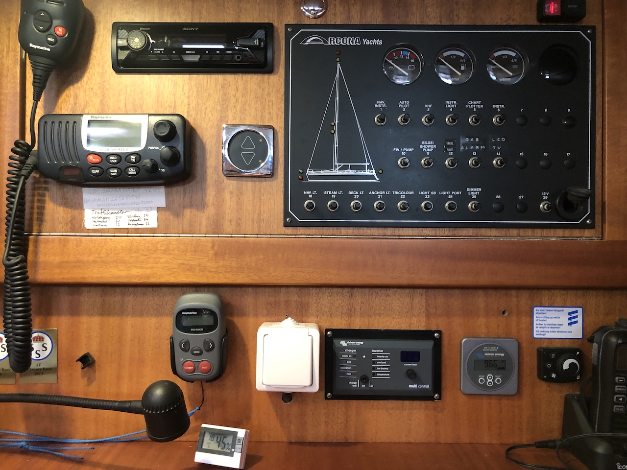
I also added a 230 W socket from the inverter next to the control panel. Easy to reach when charging, e.g. a computer from the nav station.

Greeat reading your blog
LikeLike