After so much work and preparation I could finally install my LiFeYPO4 battery!
Delivery and initial voltage check
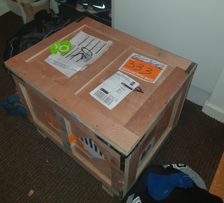
I ordered my cells from a large reseller here in Europe. They have relatively large volumes, and I would not need to pay too high shipping cost or a customs/tax/handling cost. To reduce the shipping cost, I also ordered a 12V Winston battery for a friend so we could share the shipping cost.
Batteries are considered hazardous goods, and the delivery time stated when placing my order was one to three weeks. I expected to have some time before I got the cells.
I did not expect to get a call at work six days later from the delivery firm, telling me that they had a package of 58 kg with dangerous goods that will be delivered at my apartment within 30 minutes.
Not only were the cells from the same batch, they even had serial numbers very close to each other.
When doing an initial check of all the cells, they all matched. My multimeter at home is not the best. However, it’s enough to see that all eight cells had roughly the same voltage and none of them seemed to be damaged. I will do further tests later, but this was enough to see that the cells seemed ok.

Initial charge and balancing
Since I don’t own a laboratory power supply to do the initial charging and balancing, I got some help from Jimmy Hellberg AKA Mr. Lithium AKA PacMan.
Jimmy first charged cells when they were connected in parallel and charged them with a laboratory charger at 3.6V 8A. Since the battery is 1280 Ah at 3.2V, it took quite a while.
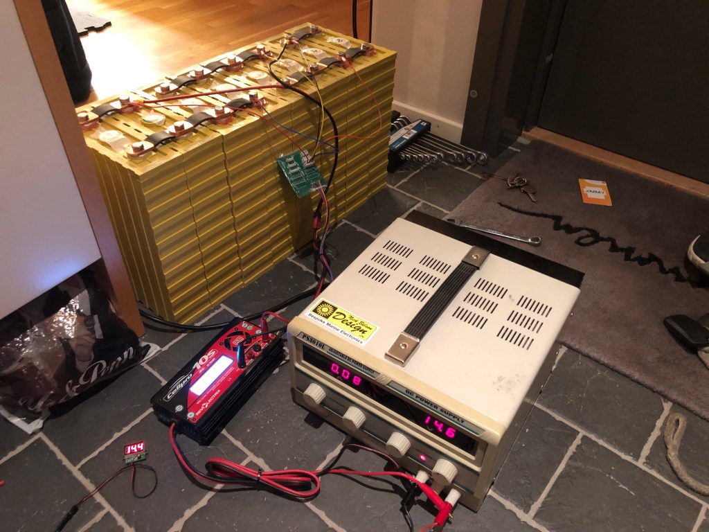
After the initial charge, the cells were top balanced with a reasonably advanced balancer. All pairs were balanced to 3.688V exactly. Had I chosen any other cells than Winston or CALB I would most likely have chosen to bottom balance instead of top balance.
Glad that Jimmy could live with my battery in his hallway during the 160 hours initial charge and then some more time until I could pick them up.
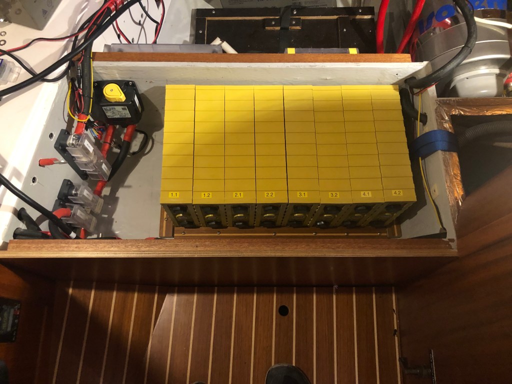
2P4S block
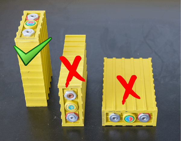
The cells are all Winston Thundersky 160AHA LiFeYPO4 (3.2V/160Ah WIDE) cells. The main issue when finding the right cells was hight. I could only fit cells with a hight of 260mm including all the cables and connectors.
The solution was to use eight cells instead of four and mount them on the side. LiFeYPO4 cells can be mounted on the side as long as all the plates are in contact with electrolyte, positive and negative in a vertical alignment.
EDIT: The recommendation has been changed by EV-Power after I installed the battery. Since 26 Jul 2019, the recommendation is that the cells should always be mounted in the upright position (terminals on the top). This has been confirmed by both CALB and Winston. According to both Winston and EV-Power some customers have had issues with their cells when they have been mounted in other positions. But neither is providing any reason why they have to be mounted in the upright position only.
By first connecting two cells in a parallel pair and then connecting the four pairs in serial, each pair will always be balanced. In theory, this means that you run the same risk of having an imbalance with eight cells as you do when having four cells.
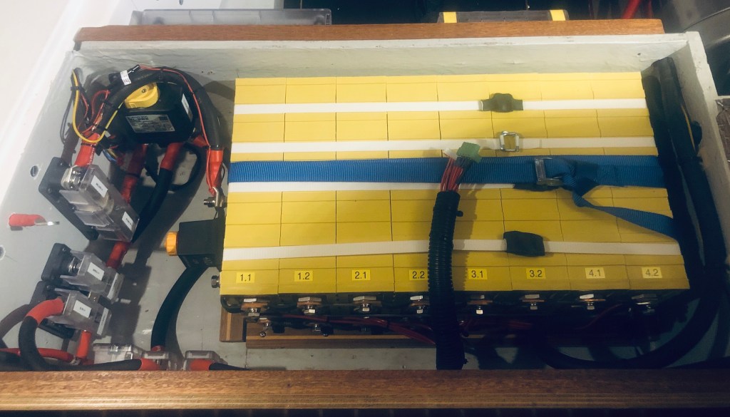
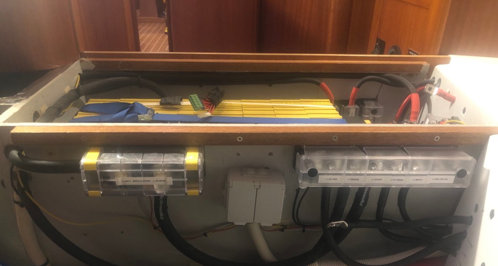
Fitting in the boat
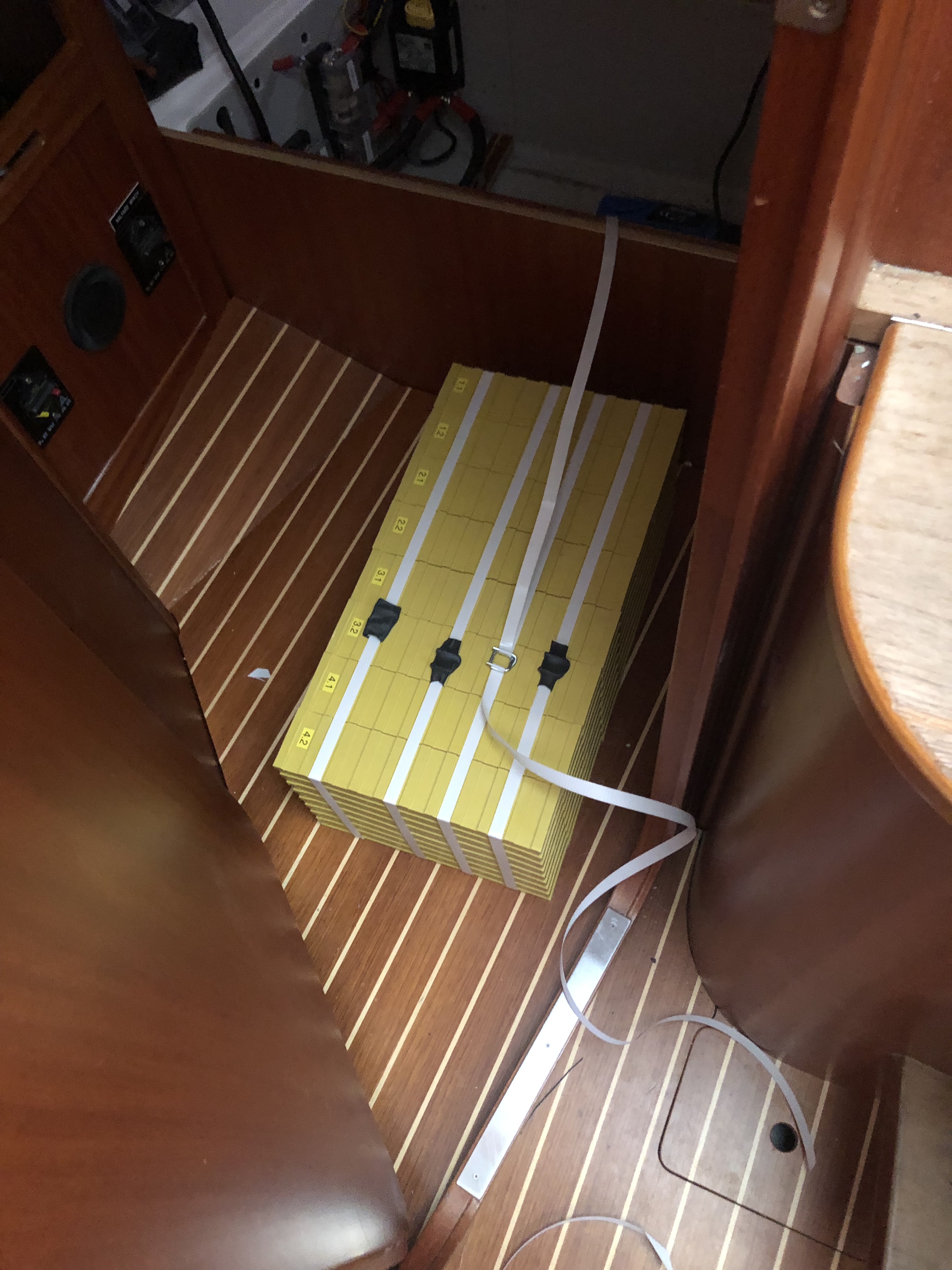
I got some cheap manual pallet straps that I was planning to use. However, I still wanted the pack to be secure in the box. I tried squeezing the pack together by hand to measure the fit of the battery holder. I will use a strap the will run twice over the battery. The strap has a breaking load of 350 kg, so I think I will be ok with just one strap to hold the battery down.
Once I had the battery holder in place, I started strapping the pack. I had expected it to be reasonably quick to strap them. However, 6 + 2 straps in a quite tight space when you don’t have any tools were quite cumbersome. The straps were also a bit heat sensitive, so I did not use heat shrink on all the straps.
It was a super tight fit when I had the loose cells in the battery holder. However, after the pack getting extremely tight with the pallet straps it was no issue getting the pack in the battery holder.
Battery Brain
The Battery Brain Type I is to be phased out by the vendor. The reason why I cannot understand.
All of Battery Brains new models, Victron Battery Protect and Alfatronix Powertector uses some current in shutdown mode. I don’t even want a small amount of current. I want a 0 (zero) load on the batteries when the low voltage is triggered.
The only under-voltage protection that draws a 0 (zero) loads when triggered is the old model, Battery Brain Type I.
I could also not use the Victron Battery Protect. These devices can be used for both over and under-voltage protection. However, they have to be connected differently depending on if they are connected to a load or a charge. Most people solve this by having one Battery Protect for the Load and a different Battery Protect connected in the opposite way for the Charge. If you connect them in the wrong way, you risk breaking them.
This works fine, but I have not figured out how to connect a Multiplus that is both a load and a charge.
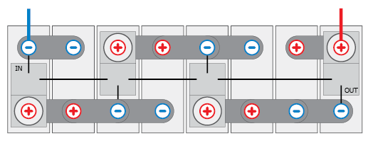
I decided to connect everything that could cause a load on the other side of the Battery Brain from the battery. In theory, this can cause some faulty values on the sensor cables to the battery monitor and the generator.
I have measured the difference before and after the Battery Brain and, the difference is so small that it cannot be measured even with my expensive calibrated Fluke. I prioritized saving the battery from under-voltage than having the sensor cables connected directly to the battery.
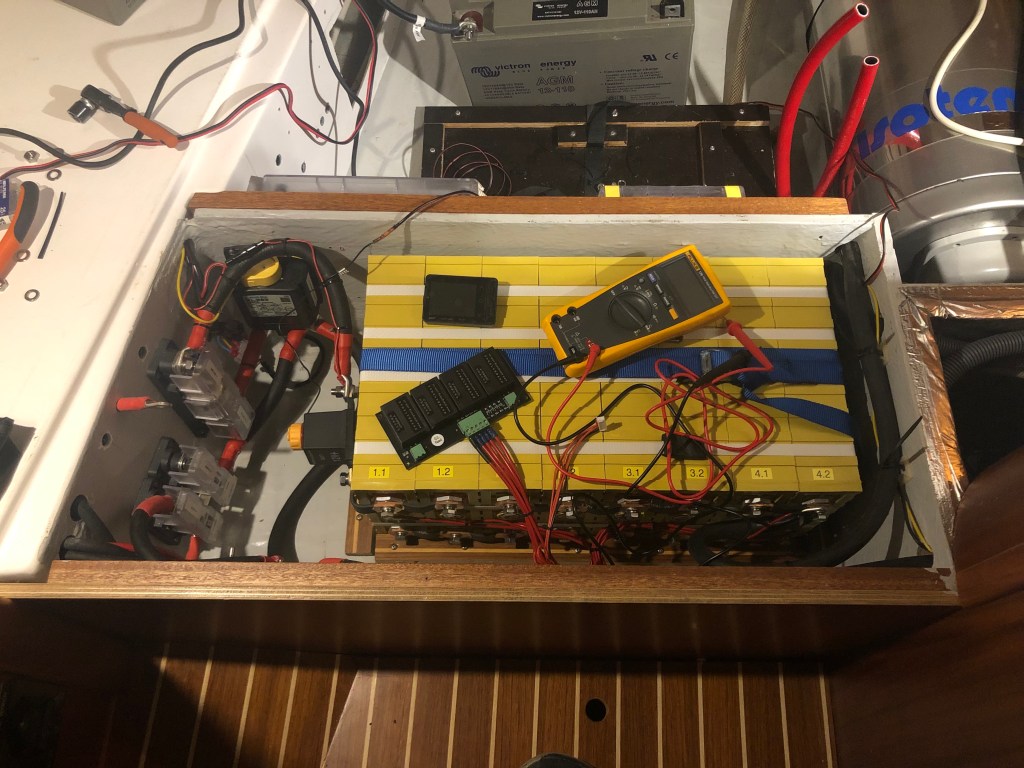
Cell logger and balancer
As I wrote before, I will not use a BMS. Instead, I will monitor the cell balance manually using a cell logger Multimeter and do the balancing manually with a dedicated balancer.
When there is not a lot of load or in the middle of the SOC scale, the difference is not noticeable. Just after I have managed to get a high SOC, e.g., after running the alternator, I will check manually using a cell logger or Multimeter. With the cables to the cell logger already connected to the battery, it is easy to connect the cell logger and check the balance.
If I do find an imbalance, I can always do a manual balancing. The balancer is not marine grade. However, since neither the cell logger or the balancer will be connected to the battery when I am not using them, I don’t see this as an issue. The balancer will be stored in a waterproof bag with silica gel bags when not used.
Most BMS systems that balance the cells do this with minimal balancing current, e.g., the BMS123 Smart uses a 1A balancing current and some other as low as 0.5A. This low balancing current is ok since they are connected all the time. But not when you do the manual balancing.
The EV lithium QNBBM balancer uses peak balancing current up to 10A and continuous balancing current of 6A. How long time will it take to fix an imbalance of my cells in real life, I don’t know yet.
Issues with the Cell Logger
Maybe I got a bad one or, the ISDT BG 8S cell logger is not as good as I had hoped.
I had bought a calibrated Fluke Multimeter with high accuracy since I wanted to see if there were any differences between Jimmy’s advanced balancer, my cell logger, and the BMV-712. However, also to be able to measure with high accuracy before and after balancing with the QNBBM balancer.
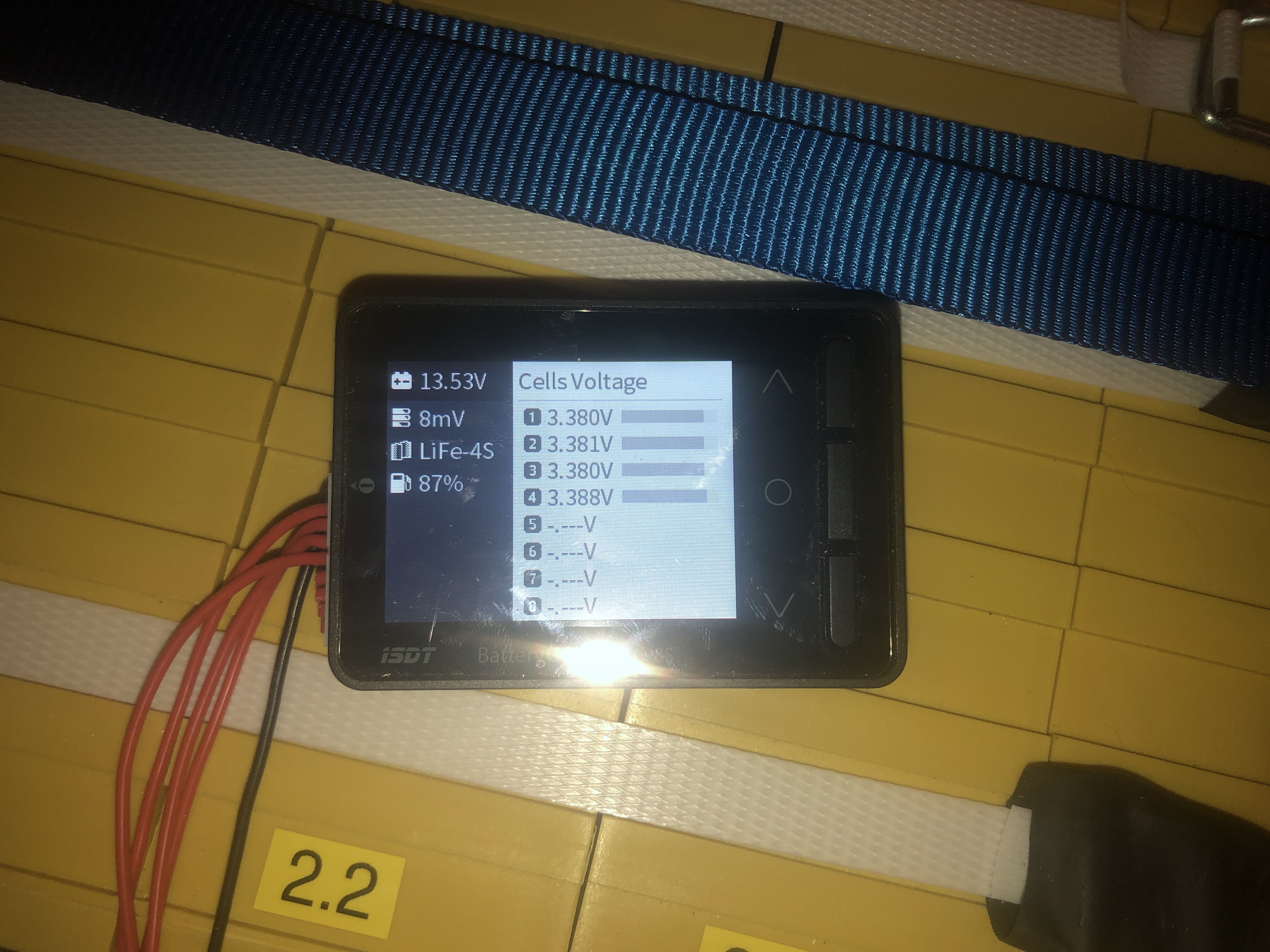
In my first cabling, I had connected the cell logger to measure all the cells. I had asked both the reseller and ISDT directly about using the BG 8S in a 2P4S solution but never gotten any response. When I connected the cell logger for the first time, I both noticed that it could not handle 2P4S and that it also showed some voltage differences that I did not expect.
I rewired the cables to the cell logger as if I only had four cells and measured the voltage on the balancing cable connection. The voltage on the balancing contact was precisely the same as on the cells. So there was no issue with the cabling, the issue was with the cell logger.
| Cell nr | BG 8S (reversed) | Fluke 179 | After 24h QNBBM balancing |
| 1:1 | 3.388 V | 3.387 V | 3.385 V |
| 1:2 | – | 3.387 V | 3.385 V |
| 2:1 | 3.380 V | 3.395 V | 3.385 V |
| 2:2 | – | 3.395 V | 3.385 V |
| 3:1 | 3.381 V | 3.394 V | 3.384 V |
| 3:2 | – | 3.394 V | 3.384 V |
| 4:1 | 3.380 V | 3.391 V | 3.383 V |
| 4:2 | – | 3.391 V | 3.383 V |
| Max diff | 0.008 V | 0.008 V | 0.002 V |
Values on cells and balancing cable with the Fluke was exactly the same. The values after the QNBBM balancing for 24h was measured with the Fluke
It would have been ok if the difference between the cell logger and the calibrated Fluke was the same on all cells. However, now the difference between the values by the cell logger and the values from the Fluke varies between 0.001 V and 0.015 V depending on which cell.
The cell logger will be excellent to see any significant differences between the cells. However, if you want an exact cell voltage, the cell logger is not accurate enough. Over time I will get more data and know if I can trust the cell logger (with a deviance table) or not.
I guess this issue also applies to most BMS systems. Usually, you get what you pay for. An advanced Multimeter that is only used for measuring costs twice as much as many complete advanced BMS systems. You wonder about the accuracy of a BMS that is supposed to do so much more than just a Multimeter and still has half the cost.
It would be interesting to see if anyone using, e.g., BMS123 Smart is having the same issue when they measure with a calibrated Multimeter as I do with the cell logger.
Since I also wanted to check that the QNBBM was working, I decided to leave the QNBBM connected for 24 hours and measure the voltage with the Multimeter afterward.
Alternator and alternator regulator?
I still have the original Volvo Penta alternator. Will I risk damaging the alternator without a regulator that measures the temperature of the alternator when I have LiFeYPO4? Yes, there will be a risk. However, we still have not decided on what alternator to use yet.
Should we risk eating belts if we install a 100A Balmar alternator with our single V-belt or should we install a 120A Balmar alternator and convert to a serpentine belt?
Will we take the risk of overcharging the battery without an alternator regulator until next winter?
We know we will install a Balmar alternator and also their MC-614 regulator. We have just not decided on which alternator and when we should install it yet.
The No-BMS installation!
Yes, I am the idiot that has installed Lithium without a BMS! However, I still have a protection of the lithium battery, and I do not risk having a BMS system messing up my lithium battery.
- Short circuit: Main fuse, fuses on all individual loads and chargers
- Under-voltage protection (11.8 V): Battery Brain Type I, ML-Series remote battery switch
- Overvoltage protection: Alarm on BMV-712 and can shut down all chargers individually with circuit breakers
- Cell imbalance: QNBBM balancer (manual)
The only automatic protection that I miss is overvoltage protection. Currently, there is only an alarm, but since I will shut everything off when leaving the boat, I see this as minimal risk.
Installation of Victron MPPT and Multiplus will be covered later. Still, have not had time to configure the Multiplus with Victrons software yet.
Thank you, Jimmy, for all the support!!!

2 thoughts on “Finally Lithium on Liv!”