The summer of 2018 was the our first summer with Liv. As I wrote in the post Choosing LiFePO4 batteries for S/Y Liv we had some issues with getting the batteries to last.
When we bought Liv I had done some survey of the batteries and had them tested. But I had not figured out all the wiring since it was not labeled at all.
The existing wiring was not standard wiring from Arcona. Instead it was added on and changed by the first owner when more batteries etc was added. We are the third owner as far as I know. No complaints about the second owner that we bought Liv from, he either knew what he was doing when performing upgrades or used professionals.


After some time trying and testing I finally figured out how everything was wired. But I could not understand why it was wired the way it was. I also noticed some issues that most likely was part of the problem of why the batteries were bad. The typical setup with plus from first battery and minus from the last battery in the house battery bank was not used at all.
- House battery bank had two minus cables to the shunt
- Battery 1, battery 2 and battery 4 were all connected to battery 3
- Mix of capacity of the batteries
- Both a battery combiner and a battery isolator used instead of just one of them
- The different loads and chargers were all connected to different batteries. All batteries had some type of load or charge connected
- Some cable ends were of poor quality or undersized cables were used
Planning changes and rewiring
We had some requirements that were not met. Since we will install lithium batteries some additional components needed to be installed as well.
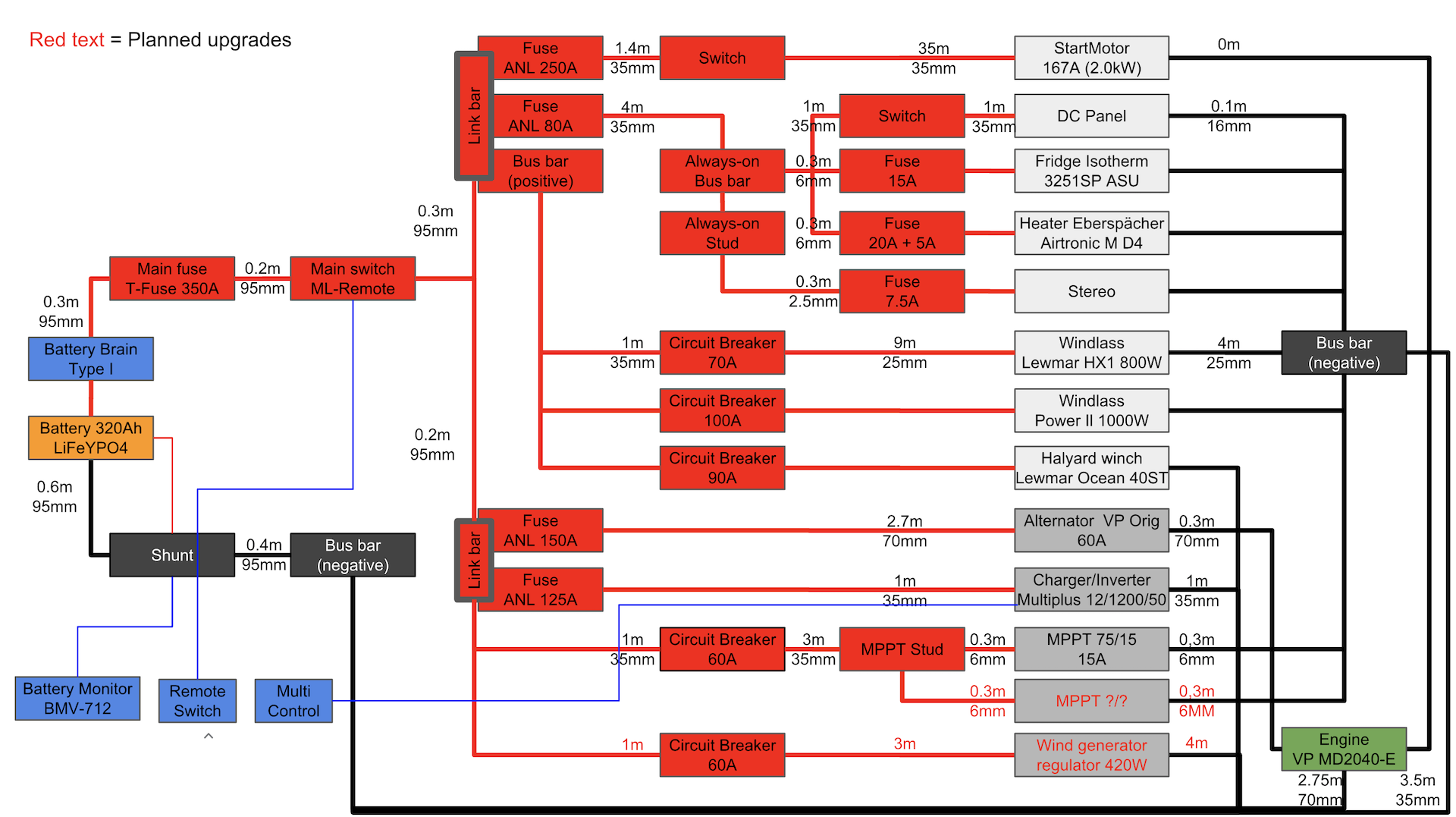
- Physically separate positive and negative bus bars as much as possible
- Main fuse and either a fuse or circuit breaker on all loads and chargers
- Marine grade cables and cable lugs (tinned copper lugs without inspection hole)
- Main switch that shuts off the battery completely from all load and chargers
- Battery monitor that supports LiFeYPO4
- Cabling for new bow windlass
- Circuit breaker for solar panels to be able to shut off solar panel charing when needed
- Prepared for additional MPPT’s and a wind generator
- Separate Charge from Load for potential upgrades in the future
Limited space for switches, busbars and fuse holders
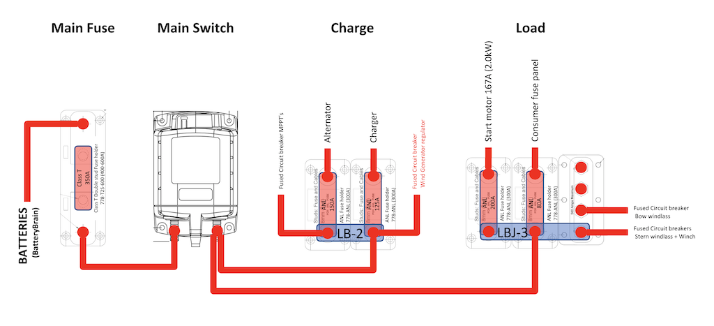
As always space is the main issue when installing stuff on boats. If I would use regular bus bars and fuse holders with cables running between every bus bar and fuse holder the amount of wall space needed would be massive.
After some searching online I found the BEP Marine Pro Installer Series with their Link Bars. The only problem was that they are not easy to get hold on for a DIY. But it could be solved with some importing and special orders at a local marine store. I really like both BEP and Blue Sea, both make really good products and are part of the same group as Mastervolt. I just wish that the companies within the same group was more compatible with each other e.g. have a link bar for connecting a Blue Sea ML-Series switch to the BEP Marine Pro Series fuse holders or bus bars.
With the Pro Installer series I could install the bus bars and fuse holders in a much smaller area. If I would not have installed the ML series remote switch I could have installed them on an even tighter space using a different link bar.
As always when you try to do stuff it always takes longer time and you have to redo stuff. Had to move the fuse holders, switches etc several times. One of many examples was that everything was nice and tidy until I got the ML-Series switch and noticed that I had to install the battery cable on the other side of the switch then what I had originally planned. Which meant that I had to move everything around one more time again.

I also wanted a physical separation for the positive bus bars and the negative bus bars, instead of trying to do the impossible thing of installing the negative bus bar in the same area. I installed the negative bus bar at a place close to where the old bus bar was located and the shunt where the battery combiner and the battery isolator was installed. With this setup the only negative from the battery in the same area as the positive bus bars are the actual negative poles on the battery cells and the negative cable from the battery.
Same issue here, things go much faster if you have everything before you start installing. The cable lugs that I made for the negative cables I first sized for BEP marines smaller bus bars. But the larger bus bar that I had ordered used M10 instead of M8 so I had to redo all the negative cable lugs. Luckily I had enough cable length that it was possible with just crimping new lugs on the existing cables.

Cable sizing and crimping
I am no electrician and had to find almost all information online. Maybe I am what some people call a fan boy 😉
Regarding cable sizing and fuse sizing I had to read a lot online as well as post some questions in different forums. Sometimes you got some really helpful responses even if some responses did not help much or were contradicting…
There is also some great wizards to calculate the needed the cable size based both on maximum current and maximum acceptable voltage drop.
- Blue Sea Circuit Wizard
- Blue Sea Choosing the Correct Wire Size for a DC Circuit
- Sutars / Skyllermarks Cable Wizard (Swedish)
Since some of these vendors are also selling products they sometimes recommend you to oversize you cables. What I ended up with choosing was to protect the cables with proper fuses and always use cables that could handle the load allowed by the fuse. For cables used for charge I used what was recommended if I could actually crimp the cable lugs myself.
For cables running from the battery to the busbars I wanted minimal voltage drop and also cables that could handle the 350 A that the main fuse was rated for. I could not make these myself and had to order them from a local retailer that had a compressor driven workshop crimp tool. Unfortunately the fitting is much harder when you are using these large sized cables and cannot crimp the cables on site. Which meant that I had to redo a couple of cables because I had miscalculated the bending radius.
All the cables and the cable lugs that I used was from Sutars/Skyllermarks. They make great cables that are tinned and use rubber which makes them much easier to work with. I also choose their cable lugs. What is great about these cable lugs is that they are double annealed tinned copper and don’t have an inspection hole. With double hexagon crimps and the heat shrink you get a really tight seal to protect from corrosion.

Since I did not have a good crimping tool to start with. I rented a crimping tool with the same brand as the cable lugs to get an exact fit when crimping. There are some cheaper crimping tools that I am not 100% sure about the crimp quality and the price for buying the Skyllermarks crimping tool is just outrageous. Luckily that crimp tool can be rented fairly cheap where you buy the cables and lugs.
Cabling for always on an DC panel
The cabling at the DC panel was already good. There was no need to redo any of the DC panel cabling. The problem was how the cables was run to the DC panel from the consumer switch and how the negative DC cables was connected to the negative stud just beside the always on stud. The negative stud was also a bit overcrowded.

Notice how close the negative cables are to the always on stud
Originally the battery cable, MPPT, always on stud and the cables running to the always on fuse holder was all run from one side of the consumer switch. On the other side of the consumer switch the actual consumer stud was connected.
I decided to run the battery cable directly to a new always on bus bar. From that bus bar I then connected all the always on connections as well as the consumer switch.
At the same time I also installed a new negative bus bar. To ease up wiring I also used this bus bar to connect the negative running from the bow windlass.
The old cables running from the batteries to the DC panel and always on was 10mm2. Even if I added the 25mm2 negative cable from bow windlass to the negative bus bar I was not worried. The new positiv and negative cables from the batteries to the DC panel area are now both 35mm2.


Multiplus
Have never had the need for an inverter before. But this time we decided to go with a charger/inverter combo.
The new compact model of Victron Multiplus has a smaller form factor than the old models. I still did not want to install the Multiplus where the old charger was located. That would have placed the charger/inverter very low and I did not want to install anything that can be damaged by water under wrist level.
The Multiplus had to be installed in one of the cabinets. This will steel some of Almas closet space, which she will let me know endlessly.
This might cause a cooling issues of the Multiplus. We will test and see if we get any problems of the air in the cabinet getting to warm when we use the boat in the summer.

Bow windlass contactor
I have yet to install the bow windlass. But when I was already doing all the cabling I wanted to prepare for the bow windlass at the same time.
The contactor for the bow windlass was installed in one of the cabinets close to where the windlass will be located. It was a bit more cables than I had expected with five small cables from the wireless remote and three small cables from the switch.

Haven’t decided how I will do yet. If I will build a small box around the contactor or if I will just tidy up the cables. Will know after I have connected the windlass to the contactor.
What remains
- Tidy up cables
- Connect bow windlass to bow windlass contactor
- Connect switch to bow windlass contactor
- Program Multiplus
- Connect Multiplus
- 230V sockets from the Multiplus
What I will not do?
- Recabling of the cables running on the DC panel
- Recabling of electric halyard winch
- Recabling of stern windlass
- Recabling of start motor
I am in no way associated with any of the companies producing or selling any of these products. The products mentioned are just the products that I used and liked. I have not mentioned some of the products that I did not like.
Thank you Båt Accenten for all the support with my special orders of Link Bars, Circuit Breakers, 95mm2 cables etc

Exciting projekt and you did a nice clean installation. We’re also in Stockholm preparing our boat during 2019/2020 for a longer trip with kids and need to go through all the wiring this year. Funny to see how many items are similar in our todo lists.
LikeLike
Kul! Vart och när sticker ni?
LikeLike
Vi har planerat att åka iväg i juni 2021 med två barn (nu 7 och 10 år), målet är i första hand Karibien (och allt som finns på vägen dit) fram och tillbaka i ett år, men vi ska se.
LikeLike